Other Team Members: Evan Phillips, Daniel McCarthy, and Brian Chang
The purpose of this project is to design and build an attitude control system for a two stage rocket. This system will utilize a cold gas propellant, such as nitrogen, to correct the rockets position in three dimensional space. This system is currently powered by an ardurino and uses an inertial measurement unit (IMU) to measure and quantify the rockets angular rate,linear velocity, and position in a global reference frame. This system will consist of 8 De Laval ( converging-diverging) nozzles , four to control pitch and yaw, two to control clockwise roll, and two to control counterclockwise roll. The overarching goal of this system is to stabilize the rocket under powered and un-powered flight, assist in stage separation, and assist in landing the booster stage (first stage) using landing legs.
Below is our major milestones to meet
1. Program the Edison board to output the IMU relative position
2. Program the Edision board to control the solenoid valve
3. Design and manufacture first iteration of De Laval nozzle
4. Program the Edision board to output roll control commands
5. Design and manufacture the roll control chassis and ACS module
6. Test, quantify, and optimize the system in roll control
7. Design and manufacture custom electronics PCB system
8. Design and manufacture a rocket with flight-rated ACS
9. Roll control test flight
10. Quantify results from initial test flight
11. Design and build an Orbitron (three axis gimbol)
12. Program the Edision board to output yaw and pitch control commands
13. Test, quantify, and optimize the system in roll, pitch and yaw control
Feature 1
The following video above shows Evan Philips demonstrating the IMU recognizing its change in roll position and outputting a signal to open of the solenoid valve(the clicking sound). This is a bare bone setup that will lead to a table top turn table where we can further configure and hone our system.
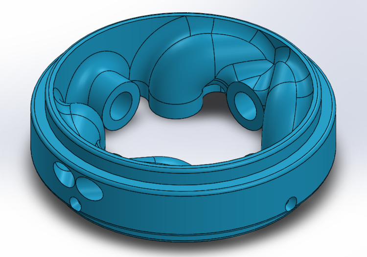
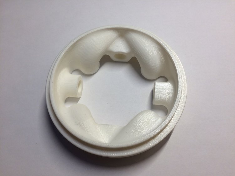
Tesla Valve
Challenge: Another method to regulate gas pressure
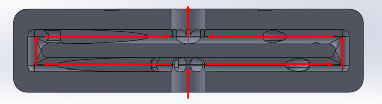
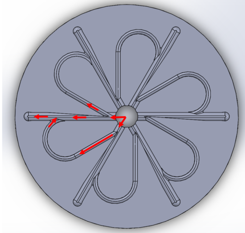
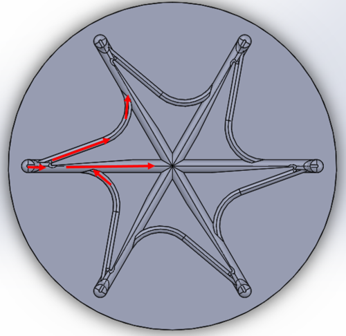
Solution: Although pressure regulators are an excellent solution in regulating pressure they are bulky, heavy, and costly. We are currently looking into alternative solutions, such as Tesla Valves. Tesla patented a design for a system to impede flow, decreasing pressure without any moving parts. The top left image is a model of his design, as the arrows depict the flow of the fluid is split into two channels, as one channels reverses the direction of the flow impeding the second channel. We took this basic concept and altered it to ideally fit our objective, thus we developed a design for a radial Tesla valve. This design has a much smaller cross sectional area thus ideal for the application for rocketry. The top right images shows the cross section view of the model, the fluid flows from the bottom then outward, then upward, and converges to a single outlet. The bottom left image shows the first "level" of this radial Tesla valve design; using the same principle of using the fluid own kinetic energy to impede its flow. The bottom right image shows the top "level" of the radial Tesla valve, this allows the flow to converge to a single outlet.

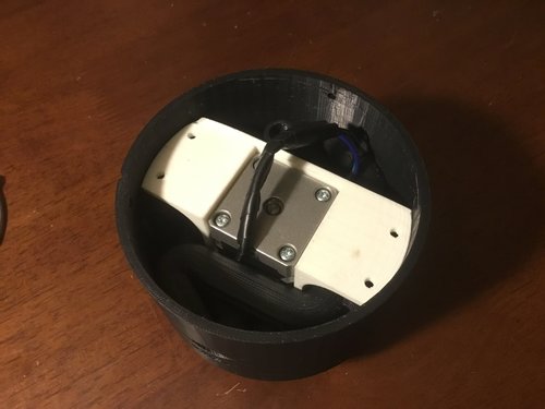
Rotary Gas Switch
Challenge: Another method to control gas flow other than Solenoids.
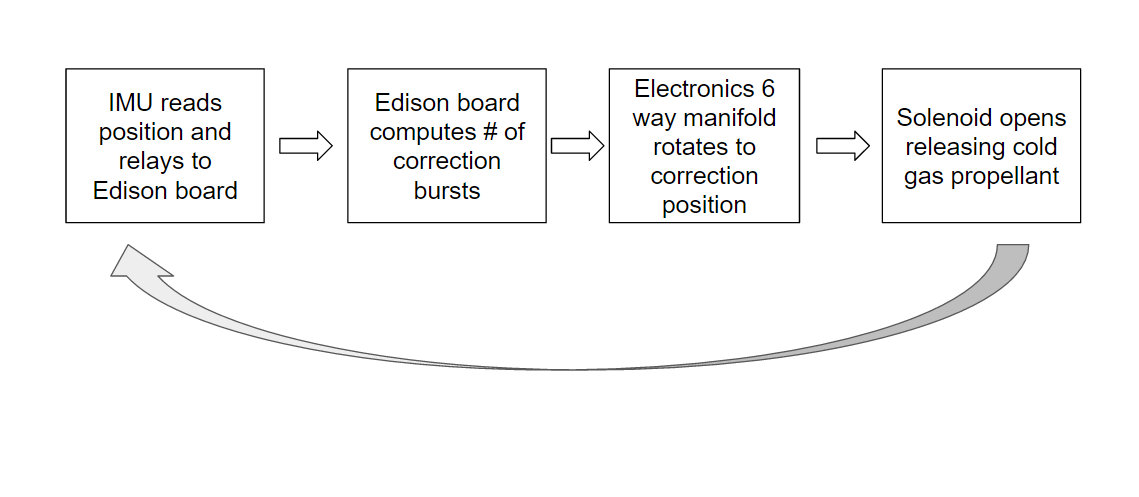
Solution: Solenoids are an mediocre solution to actuating flow, with a main disadvantage of weight. Since our system will be used for sending payload, weight is a huge commodity. Our current solution will utilizes a singe solenoid to control flow and a motorized 6 way manifold to direct the flow to its correct output nozzle. The images above depict the design, the pink is a rotating die that redirects the flow to each of the 6 outlets, it simply rotates to each possible output. We call this design and method the "Rotary Gas Switch"; The video above shows the components integration as well as its rotating manifold. The benefit of this approach is that this can be 3D printed due to the fact that is is not a pressure vessel and is only redirecting flow, thus making it a much better method than simply using 6 solenoids.


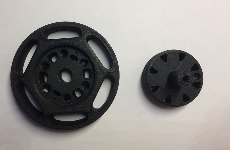

Nozzle Coupler
Challenge: Housing Roll, Yaw, and Pitch (RYP) Nozzles
Solution: In order to ensure that the nozzles are secured and are correctly position with respect to the geometry of the rocket, this nozzle coupler was designed. The method behind this was to keep the the components as simple as possible in order to reduce the overall packing volume. This coupler was designed to be housed above the "Rotary Gas Switch" and would require tubing to connect the nozzles to the "Rotary Gas Switch".


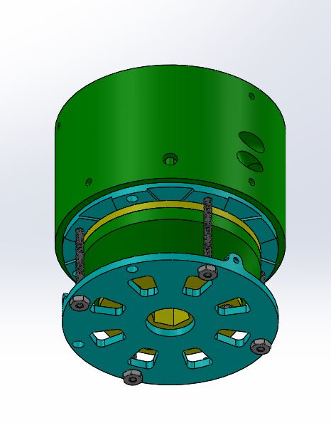
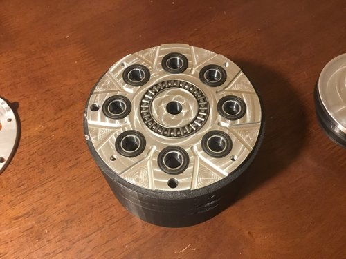
Rotary Gas Switch Package
Challenge: Optimize the packing volume by combing the nozzle coupler and the "Rotary Gas Switch" into a single system
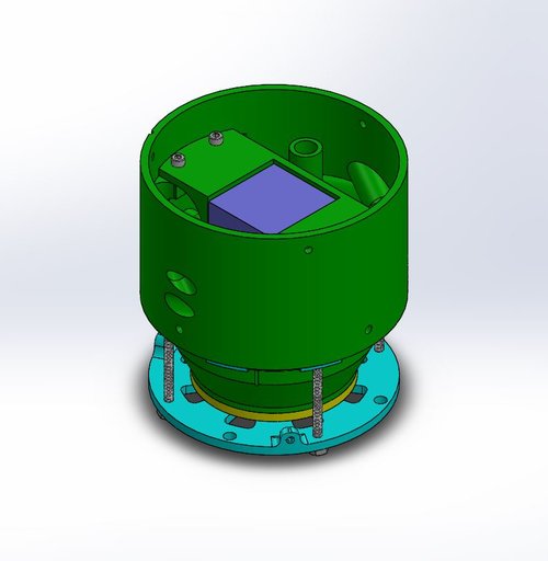
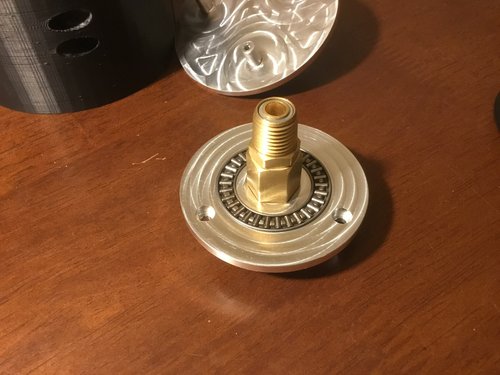
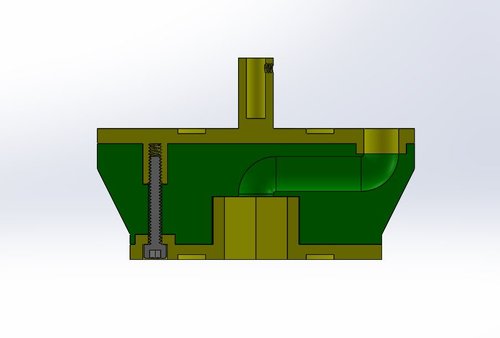
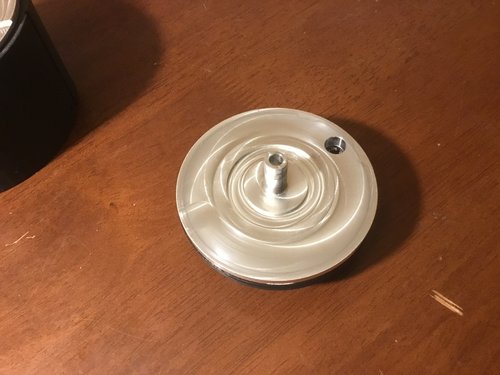
Solution: In order to reduce the amount of piping and packing volume of the ACS, the Rotary Gas Switch and the nozzle coupler was integrated into a single package. By doing so we are able to 3D print the complex piping design, in addition we will be able to electroplate the 3d printed piping to decrease friciton and increase the parts working life. Some of the major design challenges in this system was the integration of both 3d printed and CNC machined aluminum parts. The 3D printed parts consisted of the nozzle coupler and the "rotary gas switch" ( cross section shown in second row, second column). This system requires cnc machined plates due to the use of thrust bearings as well as dynamic o-rings used to seal each nozzle port.(third row, second column). The two plates that sandwich either bearings was precision machined due to the fact that the distance between each plate must be further enough to allow the thrust bearings to carry all the load yet close enough where there was still a seal on the o- rings. Other design challenges consisted of designing the T intersection where the inlet intersects the connected rolls nozzles. This is critical, for example if the intersection was closer to one clockwise roll nozzle than the other clockwise roll nozzle , one nozzle will fire first then followed by the other. Due to the fact that the roll nozzles cannot be perfectly tangential to the body of the rocket their will be be a small normal force to the body of the rocket as well as the tangential force. Thus it is imperative that both clockwise nozzles fire at the same time to "cancel out" the normal force. Finally the piping path of the set of clockwise roll nozzles must be identical to that of the counterclockwise roll nozzles, in order to accomplish this the clockwise roll nozzles and counterclockwise roll nozzles must be placed on different planes with respect to each other. This system is currently being tested.


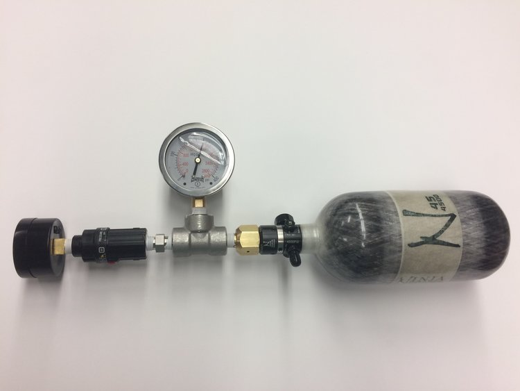
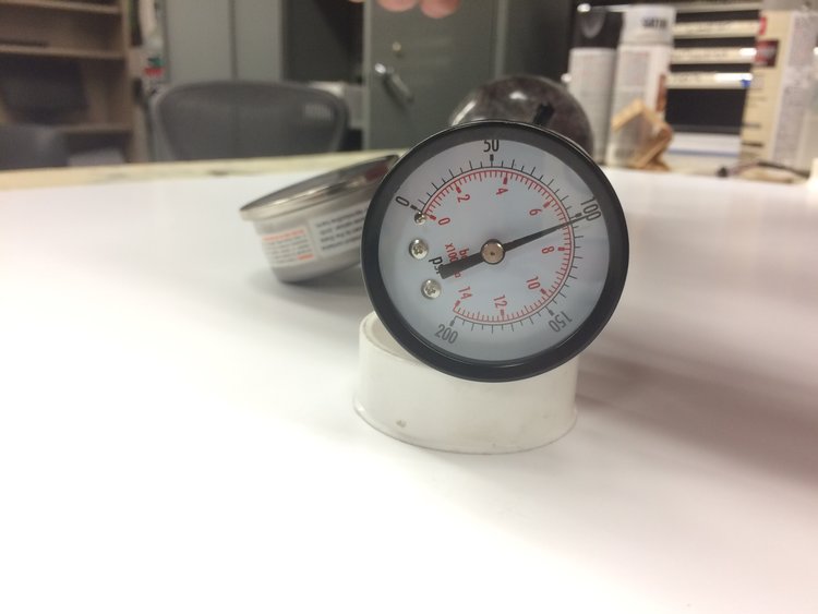
ACS Raw Demo
The video and figures above show the ACS; not including the rotary gas switch package. The two images above shows that the tank regulates the pressure to 300 psi and the second regulates it down to 100 psi; the gages will not be integrated in the final ACS. The video above shows a demonstration of the key fob feature that can be used to show case the ACS in presentations.
Roll Control Chassis
Challenge: Testing the ACS strictly in roll maneuvers
Solution: In order to test, validate, and optimize our system a testing rig was needed, thus the roll control chassis was designed and manufactured. The roll control chassis is simply a frame that will house the ACS on a set of tapered bearings, one above and one below. This allows the ACS to be freely rotated with minimal frictional forces. The roll control chassis will also house a motor that will spin the ACS to a specified RPM to test the ACS on board system and nozzle performance. A tachometer will be used to track the rpm change of the system.