Other Team Members: Evan Phillips, Chris Wellons, Thomas Chester, and Brian Chang
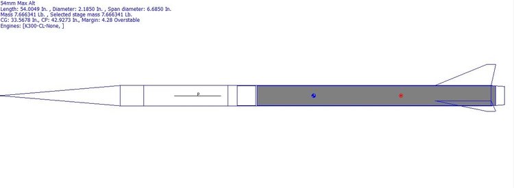
The purpose of this project is to design and build a high-powered rocket with a K-level motor for a maximum altitude competition. Some design and manufacturing challenges were how to surpass of a 5:1 thrust to weight ratio by manufacturing an efficient body tube, profile shape, and airfoil cross section of fins. Build challenges included bay mounting for electronic components, filleting and adhering fins to main body tube, and proper ejection at high altitudes. The predicted altitude that the rocket would reach is 25,000 Feet.
Competition Guidelines
1. Design and Build a Rocket with up to a K-Level Motor
2. Highest Altitude Wins(Determined by Altimeter)
3.No Staging or Clustering
4. Minimum Thrust to Weight Ratio of 5:1
5. Successful Recovery of all Parts
6. Two Attempts Permitted
Feature 2
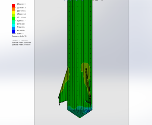
Flow Simulation of design in Solid Works. The main objective of this is to find the maximum pressure across the tip of the fin. Since the rocket is designed to be minimum diameter there are no fin tabs to anchor the fins into the motor mount. Thus the theoretical maximum pressure across the tip of the fin was need to determine the stress on the layups which laminates the fins to the main body tube.
Feature 3
Challenge: Attaching Altimeter to the rocket
Solution: Since the Altimeter utilizes GPS tracking any metal attachments may interfere with its signal transmission. Thus our solution is to mount the altimeter in the fiberglass nose cone by using a 3D printed threads and a matching coupler attached to the nose cone. The video above demonstrates our magnetic switch which can turn on and off the altimeter with a magnet.


FEATURE 4
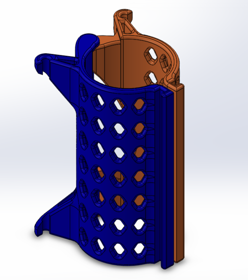
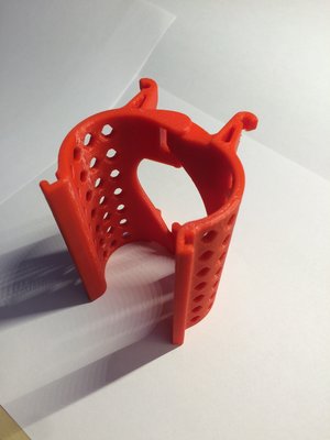
Challenge: Attaching Rocket to the launch rail
Solution: Traditionally rockets are attached to the launch rail with permanent rail guides that are bolted to the side of the rocket; increasing drag of the rocket. The solution was a removable guide that will come apart after launch. The principle behind this is a hinged assembly that is pulled apart with rubber bands allowing for separation after released from the guide rail. The video above shows an animation on the hinging action of the launch rail.
FEATURE 5
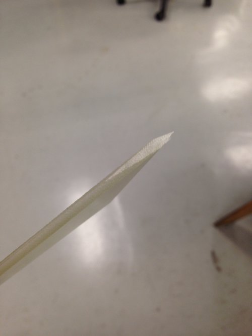
Challenge: Machining Air Foils on the fins
Solution: The unique shape and sizing of the fins proved difficult to work with. In order to cut precise and repetitive airfoils on the fins a jig was design to mount a fin at a precise angle, using a band saw precise cuts were done

Feature 6
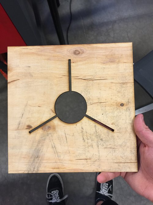
Challenge: Attaching Fins to the body of the rocket
Solution: Since the design of the rocket is minimum diameter, traditional approach of having fin tabs are impossible. A method was devised, the body tube was milled flat where it mates the fins. A laser cut guide was made to ensure that the fins were mounted equally space and were perpendicular to the surface of the body. Q-cell (fiberglass filler) was used to create the fillets.

Summary
Manufacturing of the final design spanned multiple weeks, beginning with the construction of the body tube. The fins were constructed from G-10, mounted and laid-up with carbon fiber. To save space and weight, the electronics bay was fitted into the nosecone. To decrease external surface drag, the motor was retained internally via a body-tube attachment. During the initial test flight a motor malfunction resulted in a CATO (catastrophic body failure) resulting in the immediate destruction of the rocket(Video Above).